DP Pulveriser UK - Innovating the Future of Size Reduction
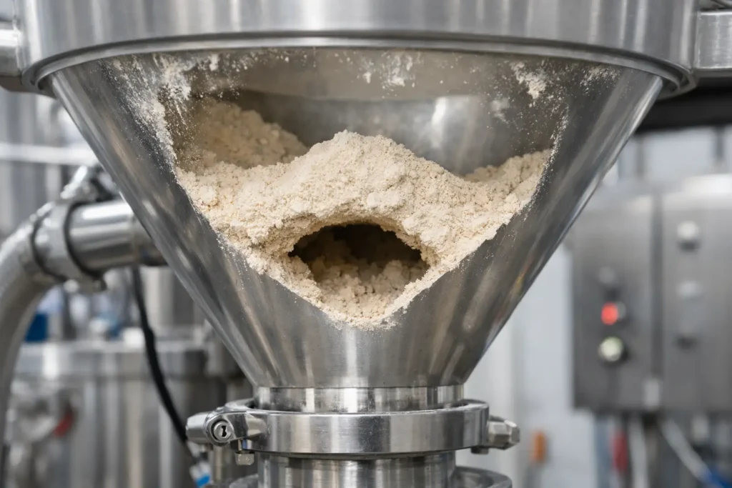
A hopper can appear adequately sized, a feeder can be correctly specified, and a production line can still stop because the material has formed a stable arch above the outlet. Why do powders bridge? In engineering terms, bridging occurs when the powder develops enough internal strength to support itself across an opening, preventing gravity from maintaining discharge. It is a material-and-equipment interaction, not simply a hopper problem.
For manufacturers handling pharmaceutical blends, food ingredients, pigments, minerals, battery materials or fine chemicals, bridging can create far more than lost throughput. It can cause batch inconsistency, interrupted dosing, manual intervention, dust exposure and unreliable downstream performance. Resolving it requires a clear view of the powder’s flow behaviour under actual operating conditions.
Why do powders bridge in hoppers and feeders?
Powder particles do not behave like a uniform liquid. Their behaviour is governed by particle size distribution, shape, surface chemistry, moisture content, bulk density, consolidation history and electrostatic charge. As a powder sits in a vessel, it may compact under its own weight. If the resulting cohesive forces are greater than the stresses encouraging the material to move through the outlet, an arch can form.
That arch may be temporary. Vibration, a pressure change or the next movement of a feeder may collapse it. In more difficult applications, the bridge is stable enough to stop flow entirely until an operator intervenes. This distinction matters because a system that only bridges intermittently can still create unacceptable variation in a continuous dosing or high-speed packaging process.
A bridge is not the same as ratholing. Bridging blocks the outlet by spanning across it, while ratholing occurs when material flows through a narrow central channel and leaves stagnant material against the hopper walls. Both indicate poor mass movement, but they require different considerations in vessel and feeder design.
The particle properties behind powder bridging
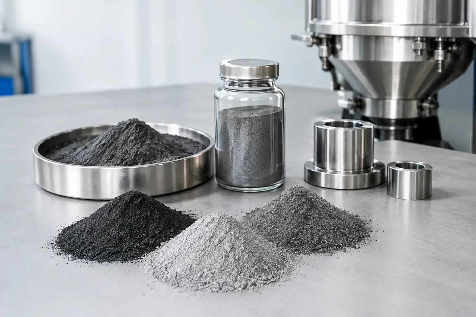
Fine powders are commonly more prone to bridging because their surface area is high relative to their mass. At smaller particle sizes, van der Waals attraction, liquid bridges and electrostatic forces can become significant. A finely milled powder may deliver the required particle size distribution for product performance, yet become harder to store, convey or feed consistently.
Particle shape also has a strong influence. Irregular, fibrous, plate-like or highly angular particles can mechanically interlock. Materials with a broad particle size distribution may present another challenge: fine fractions can fill voids between larger particles, increasing contact area and packing density. The result can be a more consolidated, less free-flowing powder.
Moisture is often the decisive variable. A small increase in humidity can create liquid bridges between particles, particularly with hygroscopic materials such as sugar powders, dairy ingredients, salts, certain minerals and pharmaceutical excipients. Conversely, an excessively dry environment may increase static charge, causing fine particles to adhere to equipment surfaces and each other.
The principal factors usually include:
- Fine particle size and a high proportion of cohesive fines.
- Irregular particle shape, low sphericity or fibrous structure.
- Moisture uptake, humidity changes or temperature cycling.
- Electrostatic charge, particularly in dry pneumatic handling systems.
- Consolidation during storage, transport or extended residence time.
These effects frequently overlap. A powder may flow satisfactorily during a short laboratory test but bridge after several hours in a production hopper because the material has had time to consolidate.
Equipment geometry can create or prevent an arch
Outlet size is one of the most important design variables. If the opening is too small for the powder’s cohesive strength, the material can establish a self-supporting arch. Increasing outlet diameter can help, but it is not always a complete answer. The transition angle, wall friction, hopper shape and material level above the outlet all influence the stresses acting on the powder.
A steep hopper wall does not automatically guarantee reliable flow. The appropriate wall angle depends on the friction between the specific powder and the equipment surface. Stainless steel finish, liners, weld quality, surface wear and product build-up can all alter wall friction over time. A geometry that functions well during commissioning may degrade as residue accumulates or as the product formulation changes.
The choice between mass flow and funnel flow is equally relevant. In a mass-flow hopper, material moves across the full cross-section, reducing stagnant zones and residence-time variation. In funnel flow, material preferentially moves through a central channel. Funnel-flow vessels can be suitable for free-flowing materials, but cohesive powders may form bridges or ratholes more readily.
Feeders must also be matched to the material. A screw feeder may compact some powders if its design, speed or inlet conditions are unsuitable. Agitated or twin-screw arrangements can provide more controlled extraction for cohesive products, but excessive agitation can alter particle structure, generate heat or create segregation. There is no universal feeder solution because the handling requirement depends on the powder and the required feed accuracy.
Milling and classification can change flow behaviour
Particle size reduction is often central to product quality, dissolution, dispersion, reactivity or downstream mixing. However, milling can also increase the likelihood of bridging when it creates a larger fine fraction, higher surface energy or irregular particle morphology. This is a trade-off that should be assessed during process development rather than after a production hopper begins to block.
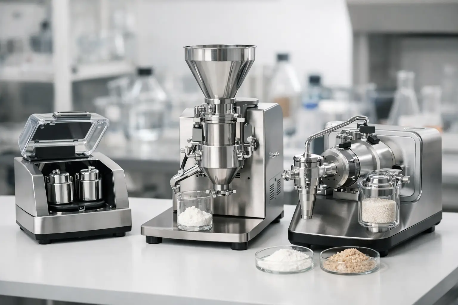
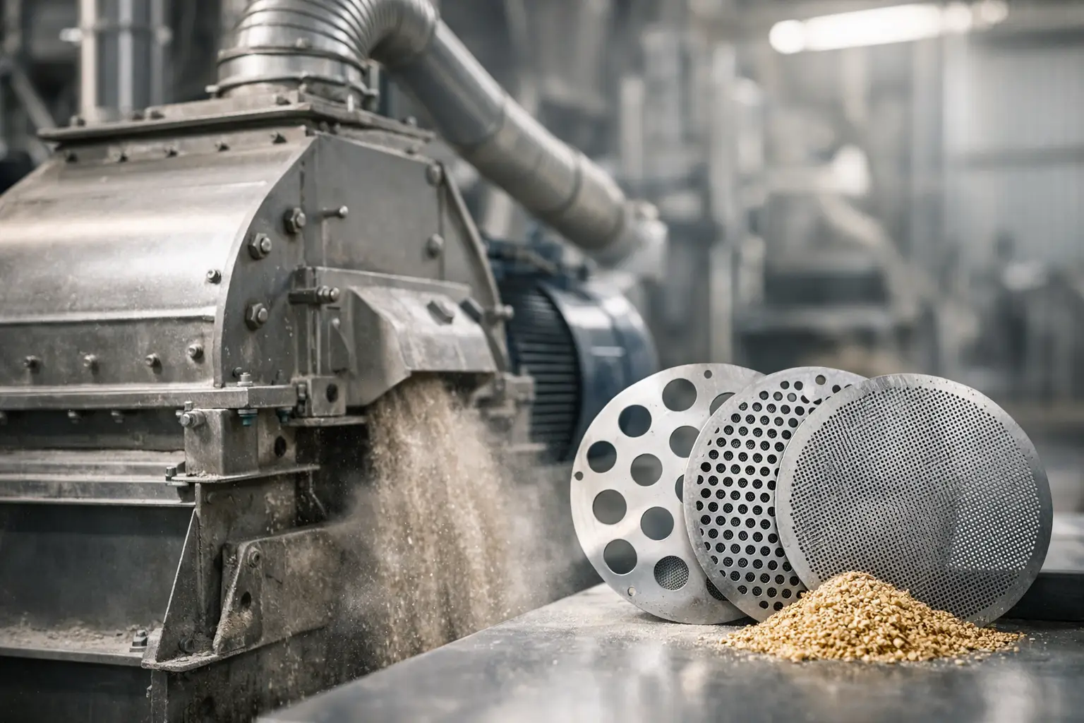
For example, a jet mill can produce very fine, tightly controlled particles for high-value applications, but those particles may require purpose-designed containment, conveying and feeding equipment. A pin mill, hammer mill or universal mill may produce a different shape and particle size distribution, with different handling characteristics. Air classification can remove oversize or control fine fractions, potentially improving consistency where the process permits it.
The objective is not simply to select a mill that achieves a target median particle size. It is to engineer a particle size reduction and handling system that delivers the required product specification while maintaining stable production. That may involve controlling moisture before milling, selecting an appropriate classifier cut point, limiting heat generation or integrating a suitable conditioning stage.
How to investigate a recurring bridging problem
The fastest route to a reliable correction is to investigate the material and the operating conditions together. Start by recording when bridging occurs: at start-up, after a particular storage period, during humid weather, at low hopper level, or following changes to a raw material supplier or milling setting. These observations often reveal the dominant cause.
Bulk density alone is not enough to specify a hopper or feeder. Flow function testing, wall-friction testing, moisture analysis and particle size characterisation give a stronger engineering basis for equipment selection. Testing should represent the real material condition, including the expected moisture range, storage time and degree of consolidation.
It is also necessary to inspect the complete line. Bridging at a hopper may be worsened by poor venting, erratic pneumatic conveying, overfilled vessels, product temperature, feeder stoppages or a discharge valve that restricts the effective outlet. Local fixes can fail when the upstream source of consolidation remains unaddressed.
Engineering measures that improve powder flow
Where geometry is the primary limitation, redesigning the hopper outlet or transition can provide a permanent improvement. Mass-flow principles, suitable wall angles and correctly sized outlets reduce the opportunity for stable arches to form. Surface treatments or liners may lower wall friction, although compatibility, wear resistance, cleanability and regulatory requirements must be considered.
For cohesive materials, controlled mechanical assistance may be appropriate. Agitators, live-bottom systems, bin activators and carefully designed vibration can encourage discharge. These methods should be applied with care. Aggressive vibration can compact certain materials, damage fragile agglomerates, create noise and fatigue equipment structures. Similarly, an agitator must be designed to promote movement without excessively shearing the product.
Environmental control can be just as valuable as mechanical modification. Dehumidified air, insulated vessels, temperature control and shorter residence times can reduce moisture-driven bridging. Effective earthing and conductive equipment design can help manage static in suitable applications, but any approach must align with the powder’s dust explosibility assessment and site safety requirements.
For critical production environments, the strongest solution is usually an integrated one: particle size reduction, classification, storage, conveying, hopper design and feeding considered as a single process. DP Pulverizer UK applies this approach when developing powder processing systems, helping manufacturers move from laboratory trials to production-scale equipment without treating material handling as an afterthought.
A bridge is useful diagnostic evidence. It shows that the powder’s strength, storage condition and equipment geometry are out of balance. Measure that relationship under realistic conditions, then engineer the vessel and process around the material rather than expecting the material to behave like a free-flowing granule.