DP Pulveriser UK - Innovating the Future of Size Reduction
A pin mill that produces the correct average particle size but a wide, shifting distribution is not calibrated for production. For operators asking how to calibrate pin mills, the objective is to establish a controlled relationship between mill settings, material condition and verified powder output. The result should be repeatable particle size reduction at the required throughput, with acceptable energy use, yield and product temperature.
Calibration is therefore more than setting rotor speed. It is a disciplined process of confirming the mechanical condition of the mill, defining a representative feed material, adjusting operating variables in a controlled sequence and validating performance with properly collected samples. This is particularly important where particle size affects dissolution, flowability, coating quality, blending performance or downstream classification.
Start with the product specification, not the mill settings
Before adjusting the machine, define what acceptable output looks like. A specification based only on a nominal mesh size is rarely sufficient for critical applications. The calibration target should normally include the required particle size distribution, such as D10, D50 and D90 values, alongside limits for oversize material, fines, moisture, bulk density and product temperature where relevant.
The production requirement matters equally. A setting that achieves a tight distribution at low feed rate may not remain suitable at commercial throughput. Establish the required mass flow, acceptable yield, maximum recirculation rate and any limits on specific energy consumption. For heat-sensitive materials, set a maximum discharge temperature before trials begin.
This approach prevents a common error: optimising for a laboratory sieve result while overlooking capacity, thermal load and consistency over an extended production run.
Confirm the mechanical baseline
No operating adjustment can compensate for worn, damaged or incorrectly assembled milling components. Isolate the equipment in accordance with site lockout procedures before inspection. Confirm that all guards, access covers and interlocks are correctly fitted before returning the mill to service.
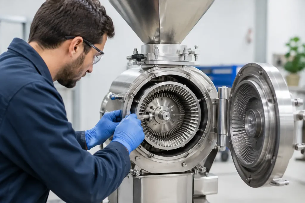
Inspect the rotating and stationary pin discs for wear, bent pins, product build-up and uneven spacing. Wear changes impact energy transfer and can alter the amount of fine material generated. Check disc alignment, shaft condition, bearing health and vibration levels. Excessive bearing play or rotor run-out can cause inconsistent clearance and accelerate component wear.
Where the machine design permits clearance adjustment, measure and record the disc-to-disc clearance at the manufacturer’s specified positions. Do not assume that a smaller clearance will always improve the result. It may increase fines, temperature, power draw and the risk of contact if thermal expansion or bearing movement occurs. For many pin mills, the clearance is a fixed engineered dimension rather than an everyday process control, so changes should only be made within the approved design range.
Also verify the condition and specification of screens, discharge arrangements, seals and collection equipment. A partially blinded screen, leaking seal or overloaded filter can make a correctly set pin mill appear unstable.
Establish a representative feed condition
Pin milling performance is strongly influenced by feedstock variability. Material hardness, friability, initial particle size, moisture content, fat content, temperature and bulk density can all change the breakage mechanism. Calibration trials conducted with unrepresentative material often fail when routine production resumes.
Use feedstock that reflects the intended production grade, including its normal moisture and particle size range. If the incoming material varies significantly between batches or suppliers, define an operating window rather than one fixed setpoint. For example, a more cohesive powder may need a lower feed rate or additional air assistance to prevent accumulation within the grinding chamber.
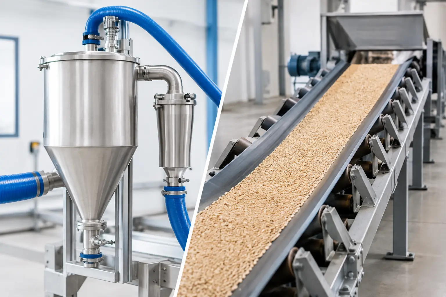
Ensure the feed system itself is stable. A loss-in-weight feeder, screw feeder or rotary valve should deliver a consistent mass flow. Pulsing feed creates fluctuating mill load, which leads directly to variation in particle size distribution. Record the actual feed rate rather than relying only on a feeder speed setting.
How to calibrate pin mills in a controlled trial
A controlled trial should change one primary variable at a time. In most applications, rotor speed and feed rate have the greatest immediate effect. Rotor speed determines tip speed and impact intensity, while feed rate influences residence time, material loading and heat generation.
Begin from a safe, conservative operating point based on the material and mill design. Run the mill until conditions stabilise, then collect a representative sample. For continuous systems, this means allowing sufficient residence time for the product in the feed, milling, conveying and collection sections to clear before sampling.
Increase rotor speed in measured increments while holding feed rate constant. Higher speed generally produces finer material, but the relationship is not linear and depends on material behaviour. At a certain point, extra speed may generate excessive fines, increase product temperature and add energy cost without a useful improvement in specification compliance.
Next, vary feed rate while maintaining the selected rotor speed. Higher throughput can coarsen the product if material passes through the grinding zone more quickly or if the chamber becomes heavily loaded. Conversely, too little feed can lead to over-grinding and unnecessary heat generation. The best setting is the one that meets the full product specification at the required sustainable capacity, not the finest possible result.
Where an air classifier, pneumatic conveying system or induced airflow is integrated with the pin mill, assess these conditions as part of calibration. Airflow can affect dwell time, removal of fines, internal temperature and the efficiency of product discharge. Changes to fan speed, damper position or filter resistance should be recorded because they can shift the final particle size distribution.
Measure output properly
Reliable calibration depends on reliable data. Use an analytical method appropriate to the product specification, such as sieve analysis, laser diffraction or image analysis. The same sample preparation and test method must be used throughout the trial. A sieve stack may be suitable for a coarse free-flowing material, while laser diffraction is generally more informative for fine powders with a tightly controlled distribution.
Take samples from the final collected product, not only from an intermediate point. Collect multiple increments over the run and combine them where a composite sample is required. One grab sample can conceal short-term variation caused by feeder cycling, product bridging or fluctuations in airflow.
Record particle size results alongside rotor speed, feed rate, motor load, product temperature, pressure differential, airflow setting and ambient conditions. Motor current alone is not a particle size measurement, but it is a useful indicator of changing mill load. Trend these values over time to identify whether variation arises from the mill or from feedstock and upstream handling.
Set the operating window and document it
Once the required output is achieved, confirm it over a production-representative duration. A brief successful run does not demonstrate capability. The mill should hold the target distribution while operating at normal throughput, with stable temperature and no progressive build-up in the chamber or collection system.
Document the validated operating window rather than a single nominal figure. This should include the permitted rotor speed range, feed rate range, air settings where applicable, approved component configuration, material acceptance criteria and sampling frequency. Define action limits as well as specification limits. If product begins to trend coarse, fine or warm, operators need a clear sequence for checking feed condition, feeder performance, airflow and mechanical wear before making unnecessary adjustments.
For regulated industries, retain calibration records, test results and component inspection findings in the batch or equipment history. This supports traceability and makes future troubleshooting considerably faster.
Recalibrate after meaningful change
Pin mills should be recalibrated after pin-disc replacement, bearing work, changes to screen or classifier configuration, modifications to conveying equipment, significant feedstock changes or prolonged shutdowns. Routine verification is also sensible where the process operates close to a particle size limit or where abrasive materials cause predictable wear.
The appropriate interval depends on the material and duty cycle. Mineral powders and battery materials may require closer monitoring of wear than relatively soft food ingredients. Hygroscopic or fatty products may demand more frequent checks for build-up and cleaning effectiveness. A risk-based schedule is more useful than an arbitrary calendar interval.
For production teams, calibration should be treated as a living process standard rather than a one-off commissioning task. A well-engineered pin mill, stable feeding system and disciplined measurement plan give operators the control needed to maintain precise particle size reduction as material and production demands change.