DP Pulveriser UK - Innovating the Future of Size Reduction
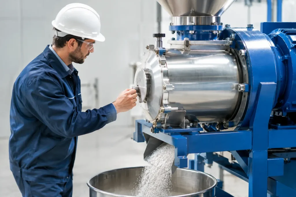
A classifier mill can produce a tightly controlled powder fraction, but only when the grinding and classification stages are set as one process. This classifier mill operating guide focuses on the operating decisions that protect particle-size consistency, throughput and equipment life in industrial production. It is intended for operators and process teams working with air classifier mills where a change in feed rate, rotor speed or airflow can materially affect the finished product.
Understand the operating window before start-up
An air classifier mill combines impact grinding with dynamic air classification. Material enters the milling chamber, is accelerated by the grinding rotor and transported towards the classifier. Fine particles that meet the selected cut point pass through with the process air, while oversize material remains in the grinding zone for further reduction.
That interaction means there is no single correct setting for every product. The operating window depends on material hardness, friability, moisture, bulk density, feed particle size, target distribution and required production rate. A brittle mineral may accept higher feed rates and rotor speeds than a heat-sensitive nutraceutical or a sticky food ingredient. Establish the process window during development trials, then document the approved settings and acceptable tolerances for production.
Before a campaign, confirm the required specification beyond a nominal top size. D50, D90, oversize limits, bulk density, flowability and product temperature may all be critical release criteria. A mill can meet a screen-based size result while still producing too many fines, excessive heat or an unsuitable particle shape.
Pre-start checks for classifier mill operation
A disciplined pre-start inspection prevents many avoidable interruptions. Verify that the mill chamber, rotor, classifier wheel, discharge line and collection system are clean, dry and correctly assembled. Inspect seals, gaskets, clamps and access doors for wear or poor seating. Air leakage can disrupt classification efficiency and create housekeeping or containment issues.
Check that the correct components are installed for the planned product. Rotor type, grinding tools, liner material, classifier wheel and filter media should match the validated configuration. In abrasive applications, inspect wear parts closely. A worn rotor or classifier wheel can alter the internal flow pattern, reduce separation accuracy and introduce contamination risk.
Confirm that all guards are fitted, interlocks function correctly and emergency stops have been tested in line with site procedures. The extraction, filter receiver and rotary valve or discharge arrangement must be ready before material enters the mill. A classifier mill relies on stable airflow; operating with a restricted filter, blocked discharge or incorrectly positioned damper will compromise both throughput and particle-size control.
For combustible powders, confirm that the system is designed and configured for the relevant dust hazard assessment. This may include earthing and bonding, explosion protection, pressure relief, isolation devices, inerting or controlled housekeeping arrangements. Safety measures must be determined by the powder, installation and applicable regulations, not added as an afterthought.
Set the three variables that control performance
Classifier speed
Classifier wheel speed is the primary control for the cut point. Increasing speed generally produces a finer product because greater centrifugal force rejects larger particles more effectively. Reducing speed permits a coarser fraction to leave the mill.
The trade-off is capacity and energy. A very fine cut can increase internal recirculation, extend residence time and reduce throughput. It may also create more fines than the product specification requires. Set classifier speed to achieve the required distribution rather than the finest possible result.
Grinding rotor speed
Grinding rotor speed controls impact intensity. Higher speed usually increases size reduction, particularly for tougher or more elastic materials, but it also raises energy input, wear and product temperature. Where a product is heat-sensitive, begin with the lowest practical rotor speed and assess whether the required particle size can instead be achieved through classifier adjustment, controlled feed rate or conditioned inlet air.
Process airflow and feed rate
Airflow transports material, removes fines and carries product to the collection system. Insufficient airflow can cause chamber build-up, unstable product discharge and broad particle-size distribution. Excessive airflow may reduce residence time, increase filter loading or carry material through before sufficient grinding has taken place.
Feed rate must be balanced against both rotor energy and air volume. An overloaded mill often produces a coarser product, higher motor load and fluctuating pressure. Start at a conservative feed rate, establish stable differential pressure and motor current, then increase in measured increments. The best operating point is typically the highest stable throughput that maintains the agreed product specification.
A controlled start-up sequence
Start auxiliary systems first: extraction or process air, product collection, discharge equipment and any cooling or inert gas supply. Once airflow is stable, start the classifier and grinding rotor according to the approved sequence. Allow the equipment to reach operating speed before introducing material.
Introduce feed gradually. Watch motor current, mill pressure, filter differential pressure, outlet temperature and product discharge during the first minutes of operation. A sudden increase in current or pressure can indicate overfeeding, a partial blockage or material accumulating in the chamber. Do not compensate by immediately increasing rotor speed. First establish whether feed rate, airflow or discharge performance is the underlying constraint.
Take an early sample once the system has reached steady state. Start-up material can differ from settled production due to residual powder, changing internal loading and stabilising temperatures. Assess the sample against the appropriate particle-size method and retain the result within the batch record.
Monitor trends, not isolated readings
Reliable classifier milling depends on recognising drift before it becomes off-specification product. Record and trend the core operating parameters: feed rate, rotor speed, classifier speed, airflow or damper position, motor current, inlet and outlet temperature, system pressure and filter differential pressure.
A stable set of values provides a useful process fingerprint. If the same material begins to require higher rotor current at an unchanged feed rate, investigate material moisture, screen or filter restriction, worn parts, bearing condition and possible build-up. If product becomes coarser without a setpoint change, check classifier wheel cleanliness, air leakage, fan performance and actual rotational speed.
Particle-size testing should be frequent enough to reflect the risk of the application. High-value pharmaceutical intermediates, pigments and battery materials may require a more intensive sampling plan than a lower-risk mineral filler. The principle remains the same: adjust one variable at a time, allow the process to stabilise and confirm the effect with representative samples.
Troubleshooting common classifier mill issues
When throughput falls, begin with the material and air path. High moisture, poor feed consistency, a bridged hopper, restricted feeder, blocked rotary valve or loaded filter can all limit output. Increasing mill speed may mask the issue temporarily while increasing energy use and wear.
A coarse product commonly points to excessive feed, insufficient classifier speed, inadequate grinding energy or reduced airflow. An overly fine product can result from high classifier speed, low feed rate or extended residence time. In either case, compare current operating data with the approved process fingerprint before making changes.
Build-up inside the chamber is more likely with fatty, hygroscopic, low-melting or electrostatically active powders. Product conditioning, cooler process air, a different feed arrangement, anti-static measures or an alternative mill configuration may be more effective than repeated cleaning. Material behaviour should guide the solution.
Unexpected contamination requires immediate investigation. Check wear surfaces, gasket integrity, upstream equipment, magnets where appropriate and cleaning controls. For regulated or high-purity applications, component traceability and inspection records support both product quality and root-cause analysis.
Cleaning, maintenance and changeover discipline
Cleaning is a process control, not simply a housekeeping task. Follow a documented method that reaches the milling chamber, classifier, product contact ducting, receiver and filters as required by the application. Verify cleanliness using the method appropriate to the material risk, whether visual inspection, swabbing, analytical testing or allergen controls.
Preventive maintenance should focus on components that influence particle-size control and mechanical reliability. Inspect grinding tools, liners, classifier wheel, bearings, seals, drive belts or couplings, vibration condition and instrument calibration at defined intervals. Replace wear parts before dimensional loss affects performance. Planned maintenance costs less than an unplanned shutdown and protects repeatability between batches.
For plants scaling from pilot work to commercial output, retain the development data that explains why each setting was selected. A full-scale classifier mill will not always operate at a simple linear multiple of laboratory conditions. Air volumes, heat transfer, feed presentation and product collection all change with scale. DP Pulverizer UK can support this transition with application-led trials and engineered milling systems configured around the required product and production duty.
The strongest operating practice is simple: treat the classifier mill as a controlled system rather than a standalone grinder. When the feed, air, rotor and classifier are kept in balance, the result is more than a fine powder – it is predictable output that production, quality and maintenance teams can rely on.