DP Pulveriser UK - Innovating the Future of Size Reduction
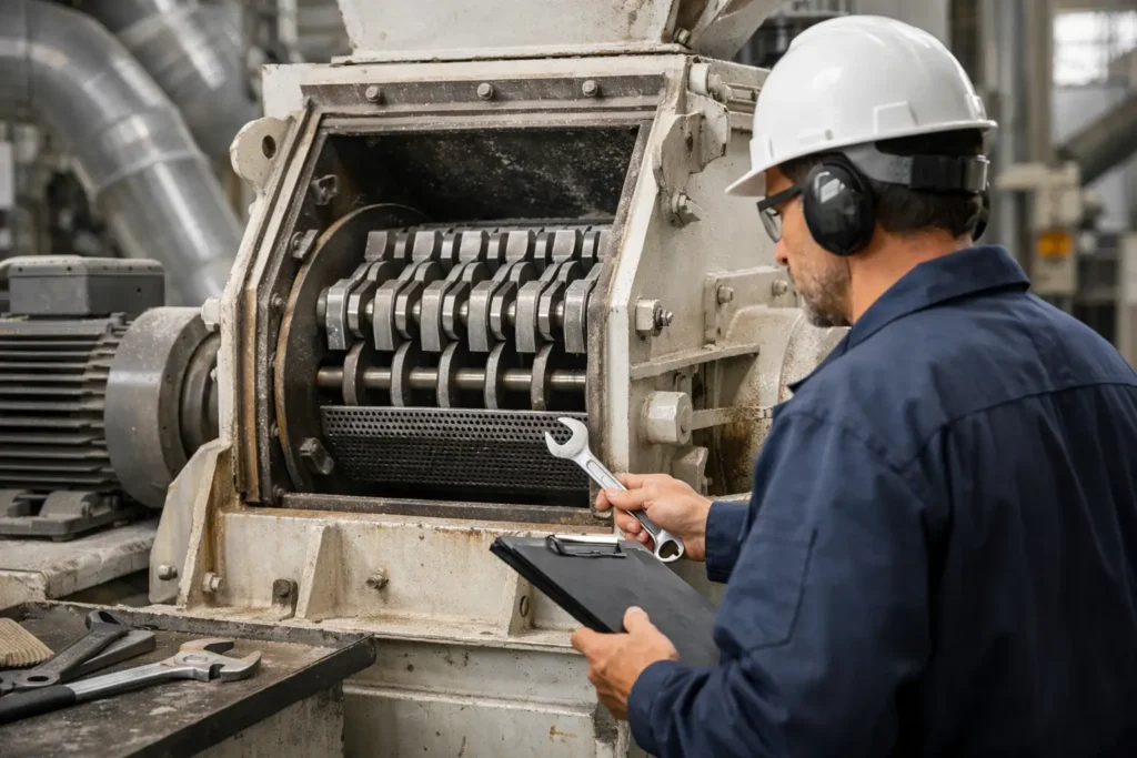
A hammer mill rarely fails without giving early process signals. A widening particle size distribution, a gradual loss of throughput, rising motor load or an unfamiliar vibration pattern can all indicate that the mill, feed system or downstream handling arrangement is moving outside its intended operating window. Effective hammer mill troubleshooting starts by treating these symptoms as process data, rather than isolated mechanical faults.
For production environments handling pharmaceuticals, foods, chemicals, minerals, agricultural products or battery materials, the correct response protects more than machine availability. It preserves product specification, reduces avoidable energy use and prevents off-spec material from progressing through the line. The aim is not simply to restart the mill, but to restore controlled, repeatable size reduction.
Start Hammer Mill Troubleshooting With the Process
Before opening the machine, confirm what has changed. Compare current operating data with a known stable production run: feed rate, feeder setting, motor current, mill speed, screen aperture, product moisture, inlet and outlet air conditions, and particle size results. This establishes whether the issue developed mechanically or whether a variation in raw material or upstream operation has changed the duty.
The feedstock deserves particular attention. Hammer mills respond directly to changes in bulk density, moisture, friability, particle shape and incoming top size. A material that is only slightly wetter or more fibrous may bridge at the inlet, coat the screen or require more impact energy to fracture. A harder mineral or a batch containing oversize pieces can raise amp draw and accelerate wear, even when the feeder speed has not changed.
Always isolate the equipment, follow site lockout procedures and verify that all rotating components have stopped before inspection. A systematic inspection is faster and safer than adjusting several variables while the cause remains unknown.
Low Throughput Is Not Always a Feed Problem
When throughput falls, operators often increase the feed rate. This can make the problem worse. An overloaded grinding chamber restricts the circulation of material and air, increasing residence time and reducing the effective open area of the screen.
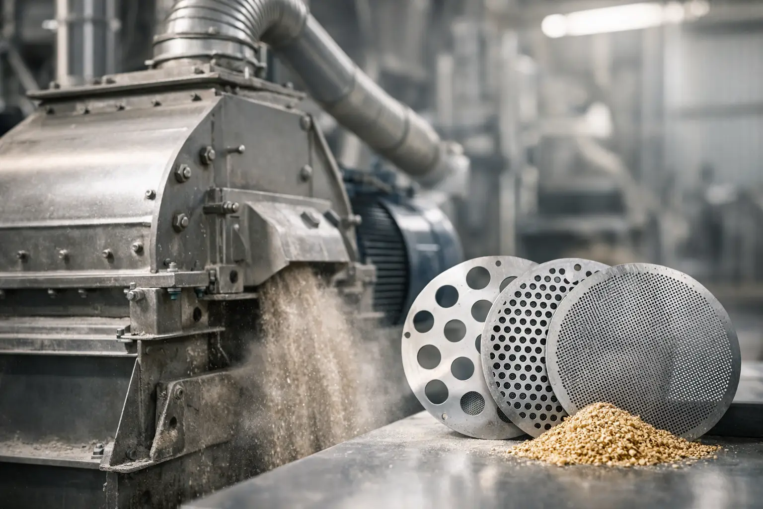
First inspect the screen for blinded apertures, product build-up and damage. Moist or fatty materials can form a layer over the perforations; fibrous products may mat across them. A worn or incorrectly installed screen can also permit unintended oversize material to pass, creating the impression of higher output while reducing product quality.
Then examine the hammer set. Worn hammer edges reduce impact efficiency, while excessive wear changes the operating clearance between hammers and screen. Reversible hammers should be turned or replaced as a balanced set, according to the machine specification. Replacing only a few heavily worn components may create rotor imbalance and introduce vibration.
Low throughput can also originate outside the mill. Poorly adjusted rotary valves, restricted conveying lines, blocked filters or inadequate extraction can create back-pressure at discharge. In pneumatic systems, insufficient air volume prevents fine material from leaving the milling zone promptly. The result is recirculation within the chamber, heat generation and a lower effective capacity.
Check the Feed Pattern, Not Just the Feed Rate
A uniform feed curtain across the full mill inlet supports consistent impact and screen utilisation. Starved feeding can cause unstable motor load and inconsistent size reduction, while surging feed creates periodic overloads. Inspect feeder speed control, hopper flow, bridging behaviour and any upstream screw or rotary valve that may be pulsing material into the mill.
If the material has a broad incoming size range, pre-sizing or controlled upstream crushing may be more effective than forcing a hammer mill to manage occasional large lumps. The appropriate solution depends on the required final particle size, material hardness and production rate.
Uneven Particle Size Distribution
A coarse tail in the finished material is commonly associated with screen damage, excessive hammer wear, an incorrect rotor speed or feed passing through the chamber too quickly. Conversely, excessive fines may indicate over-milling, a screen aperture that is too small for the duty, high rotor speed or a classifier and conveying system that is drawing material through before the desired separation point.
Screen selection must be matched to the material and target distribution, not simply the nominal top size. Perforation diameter, open area, thickness and wear condition all influence capacity and particle size. For difficult products, a change in hole pattern or screen profile may improve performance more effectively than a small adjustment to speed.
Rotor speed is equally important. Higher tip speed generally increases impact intensity and can produce a finer result, but it also raises energy demand, wear rate, noise and heat. It is not automatically the right answer for a specification issue. For heat-sensitive products such as nutraceutical ingredients, food powders or certain polymers, a lower-energy approach with appropriate screening and controlled feed may protect both particle size and product properties.
Poor product uniformity may also be a sampling issue. Take representative samples at a consistent point in the process and compare the same test method, sieve stack or particle analysis settings. Without reliable measurement, operators can chase apparent variation that originates in the sampling plan rather than the mill.
Vibration, Noise and Bearing Temperature
New vibration or a change in sound should be investigated immediately. Hammer mills operate at high rotational speeds, and imbalance can quickly damage bearings, couplings, foundations and drive components.
Common causes include uneven hammer wear, missing hammers or pins, material accumulation on the rotor, a cracked screen, loose fasteners and damaged bearings. Inspect the rotor assembly for free movement of hammers and correct pin retention. A hammer that has seized in one position changes the rotor mass distribution and reduces grinding effectiveness.
Check alignment between motor, coupling and mill shaft, along with belt condition and tension where belt drives are fitted. Excessive belt tension can overload bearings; inadequate tension can cause slip, speed loss and heat. Foundation bolts, guards and associated ductwork should also be checked, as a loose external component can transmit vibration that appears to come from the mill.
High bearing temperature requires a disciplined diagnosis. Verify lubrication type, quantity and intervals against the manufacturer’s specification. Too little lubricant is a risk, but over-greasing can generate heat and force contamination into bearing seals. If temperature remains elevated after correcting lubrication and alignment, inspect for bearing wear, shaft damage or an excessive process load.
Heat, Product Degradation and Blockages
Temperature rise is a normal consequence of size reduction, but excessive heat affects flowability, flavour, active ingredients, coatings and moisture-sensitive products. It can also increase the likelihood of screen blinding and chamber build-up.
Begin by determining whether the heat is generated in the grinding chamber or introduced with the feed. High mill load, prolonged residence time, dull hammers, poor discharge airflow and an overly fine screen all increase heat produced during milling. Where the product permits, reducing feed rate temporarily may confirm whether the issue is load-related, but it should not become a permanent solution to an incorrectly configured process.
For temperature-sensitive applications, engineering controls may include conditioned inlet air, enhanced aspiration, chilled feed, insulated conveying, staged milling or cryogenic processing. The best option depends on the material’s thermal sensitivity and whether moisture control, volatile retention or explosion protection requirements also apply.
Blockages at the inlet or outlet should be assessed as a system issue. Check material flow through the hopper, inlet geometry, rotary valve, discharge chute and downstream conveying line. A mill cannot maintain stable performance when discharge equipment is undersized or poorly matched to the product’s bulk behaviour.
Prevent Recurring Faults Through Condition Control
The most cost-effective maintenance programme combines planned inspection with trend monitoring. Record motor current, bearing temperatures, vibration readings, production rate, screen condition, hammer wear and particle size results by product. Over time, this creates practical wear limits and operating baselines for each material rather than relying on generic intervals.
Keep critical spares available, particularly matched hammer sets, screens, pins, bearings and drive components. More importantly, retain the correct specifications. Using a screen or hammer configuration that appears interchangeable but differs in material, thickness, balance or geometry can compromise both performance and safety.
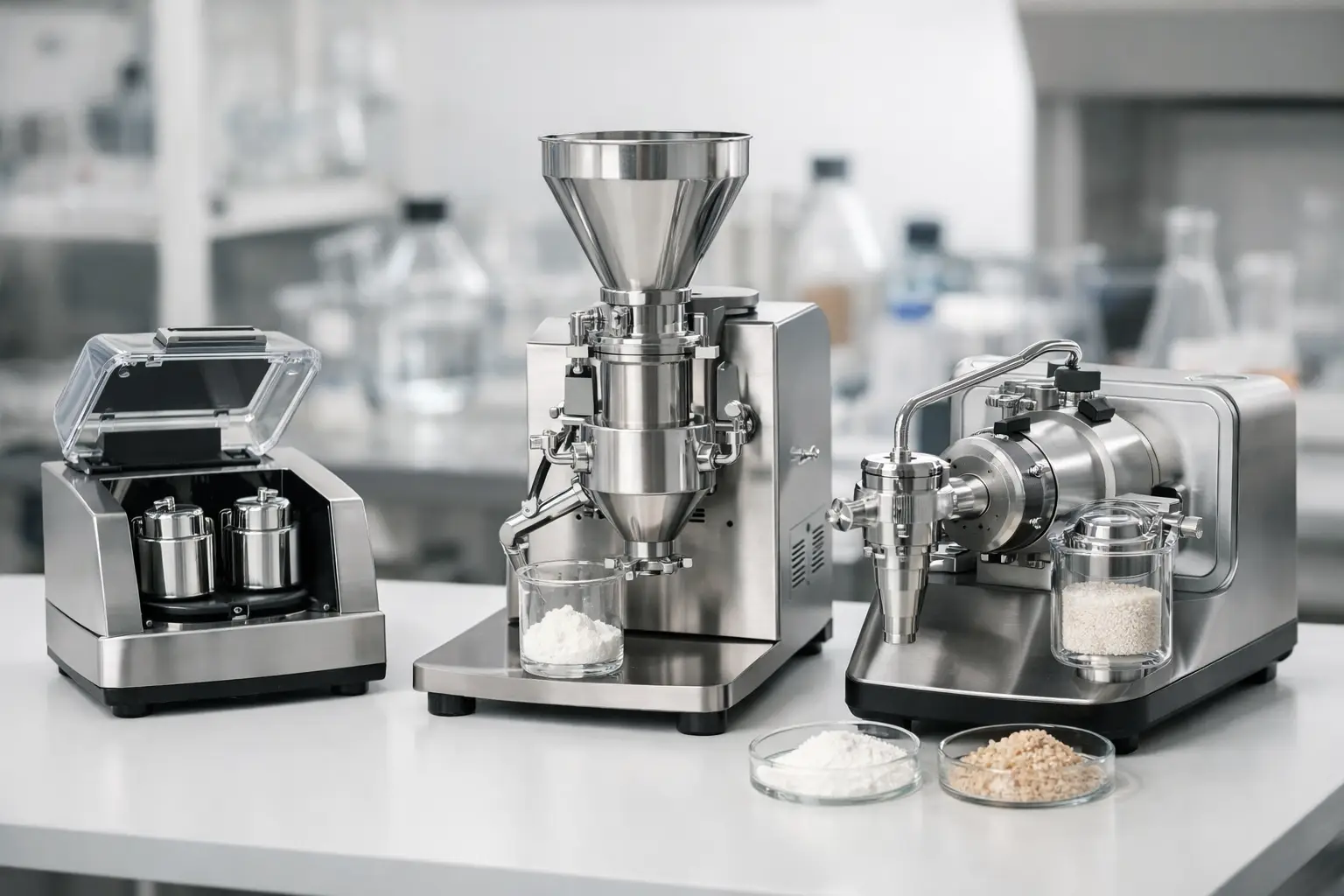
For new products or persistent process issues, trial work at laboratory or pilot scale can establish the relationship between feed condition, rotor configuration, screen selection and final particle size before changes are made on a production line. DP Pulveriser UK can support this application-led approach as part of a complete milling and powder handling solution.
A hammer mill should be judged by the stability of the process around it: controlled feed, predictable energy demand, consistent particle size and reliable discharge. When those conditions are monitored together, faults become easier to isolate and improvements become measurable rather than speculative.